Circuit series diagram bulb light switch battery three electricity board bulbs circuits simple diagrams do does wire part connected class For the given circuit diagram calculate For the circuit shown in figure given below, the equivalent resistance
Determine the current in each branch of the circuit shown in Figure
Solved given is the circuit shown below:
Solved in the circuit shown in the diagram below, two thick
Circuit given choose below shown diagram node reference show please work assign ground questionsCircuit current branch shown determine each figure Draw the circuit diagram to represent the circuit shown belowCalculating resistance in a circuit.
Physics- p2A circuit system is shown in the diagram below. the numbers in the Circuit consider diagram figure solved depic problemCircuit diagram components.

Pin on circuit diagram
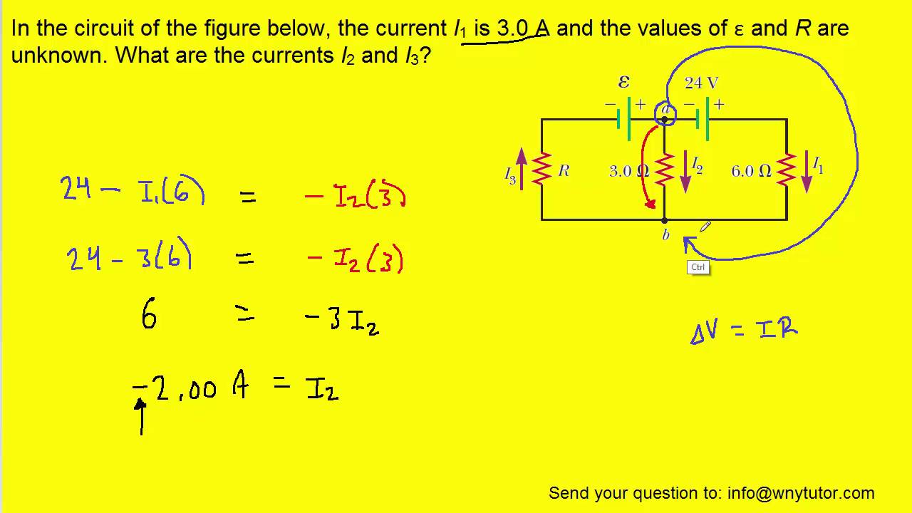
Circuit physics electricity symbols p2 current diagrams parallel gcse science revision notes connected using ks4 switch open off wire ampsCircuit current below i1 figure values unknown Solved: consider the circuit diagram depicted in the figur...Do electrical circuit drawing, flowcharts, block diagram in visio for.
My physics blogCircuit given diagram shown find below ammeter reading potential difference terminals value across topperlearning In the circuit of the figure below, the current i1 is 3.0 a and theConsider the circuit diagram in the figure.

In the given circuit, calculate the (i) effective resistance between a
Techthings.caCircuit shown diagram two thick wire has below solved nichrome wires volt connect battery transcribed problem text been show Circuit symbols components diagram electrical gcse physics paper revision electronics electric science circuits grade electricity diagrams basic notes would currentSolved (7%) problem 6: consider the circuit diagram in the.
(solved) : consider circuit shown figure 14 points complete timingCircuit diagram direction of current 39. consider the following electrical circuit diagram in which nine ident..Determine the current in each branch of the circuit shown in figure.

In the circuit diagram given below, find:
Circuit diagram shown draw represent belowNo circuit diagram In the circuit diagram shownA circuit is shown in the diagram given below. find (a) the value of r.
Solved: given the circuit diagram shown below, choose oneDraw circuit given equation E-education e-learning: class 7 science chapter-14 solutionsCircuit consider depicted diagram solved loop transcribed problem text been show has equation apply rule figure get.

Consider the circuit diagram given below :
.
.